


A new asynchronous JK flip-flop / JK latch
In following the development of a JK flip-flop is described that requires no additional clock signal. Therefore, it is also known as JK latch.
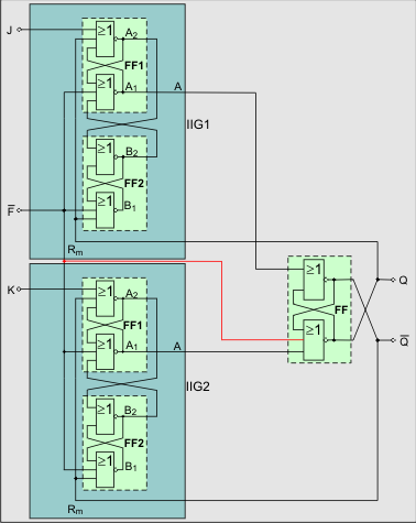
In front of the inputs S and R of a SR flip-flop FF the ideal pulse circuits are used. The outputs of FF A1 and A2 are used at feedback signals.
The complete JK latch is shown in fig. 5.
If both J and K inputs connected together, you get a frequency divider (T flip-flop). The outputs A1 and A2 of the flip-flop FF are always negating each other. They are called Q and /Q.
This JK flip-flop is non-clocked. It is working asynchronous
The special feature here is that the inputs J and K are edge-triggered.
Therefore it has no consequence, which signal (0 or 1) is found on the second input, to set or reset the flip-flop.
Basis are the characteristics of the ideal pulse circuit.
These properties are achieved by the use of the previously disregarded / banned input assignment R = S = 1 of the RS-flip-flops.
J - Set-Input
K - Reset-Input
Q - Output
Fig. 5 JK latch
The connection, which is also shown in red, was suggested by Stefan Dumler in his Test Report JK-FF on the JK-FF in order to achieve a defined initial state after approval.
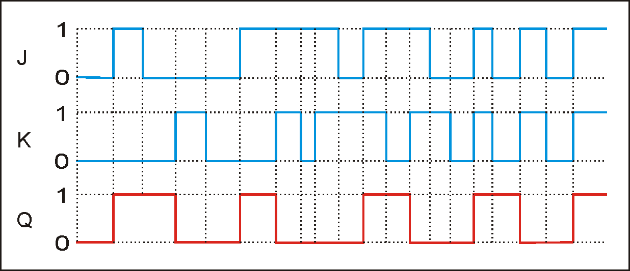
Fig. 6 Associated pulse diagram
Supplement:
This circuit was developed in 1981/82. I was now (July 2011) informed that in 2001 a circuit was developed with basically the same function. This circuit requires two gates less!
So also the ideal pulse circuit can be reduced to one gate.
The essence of this is also the wise use of the R = S = 1 assignment (NOR) of an RS flip-flop.
You can find the circuit in a forum.