


The RS flip-flop
To animation
The RS flip-flop is the simplest of all flip-flop types and itself forms the basis for other flip-flop circuits. For the explanations on this
site it is assumed that the RS flip-flop is constructed with NOR gates (see Fig. 1). This is not a limitation. When using NAND gates, only the
corresponding conversion rules need to be observed.
A 1 signal at S while R has a 0 signal (S = 1, R = 0) sets the flip-flop (Q1 = 1, Q2 = 0), while (S = 0, R = 1) resets the flip-flop
(Q1 = 0, Q2 = 1). With the subsequent transition to S = R = 0, the corresponding initial state is retained (saved).
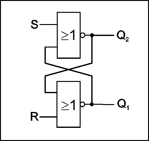
Fig. 1 RS flip-flop
But what happens now if both inputs receive a 1-signal (S = R = 1)?
If you look in specialist books or on the Internet, you will find explanations of the RS flip-flop and the associated truth tables including
statements such as:
- "R = S = 1 is forbidden or absolutely to be avoided or nonsensical"
- "R = S = 1 is unstable / metastable"
- "R = S = 1 leads to an unstable or metastable state"
- "R = S = 1 does not lead to a change of state"
We will critically examine this nonsense in the following.
What should a correct truth table look like?
Basics
When an RS-Filpflop is generally referred to, it is understood to mean the hardware implementation of the flip-flop by
means of two feedbacked NOR or NAND gates. The simplest implementation of such a NOR gate is a simple transistor with collector and base resistance.
If identical components are used for both gates, there are also no preferred positions such as priority setting or resetting, for example when
applying the supply voltage.
That is the basis for all explanations of this circuit together with the corresponding truth table! (also called status table)
A truth table shows the static final state of a system with a defined input assignment. In order to represent transition states, graphs are used
with corresponding nodes that represent the different states.
A truth table must record all possible states that occur with different input assignments of the examined circuit - in this case the RS
flip-flop. A special application is irrelevant. The user / developer then decides for himself how to use certain properties sensibly and what he
has to pay particular attention to. Since this circuit has so far only been put into a stable memory state by alternative control of the two inputs,
one speaks in this case of setting and resetting a memory. Accordingly, the two inputs are referred to as S (Set) and R (Reset). But that is
arbitrary. For example just E1 and E2 would also be possible. Then many would not have considered it illogical, contradictory
or absurd if both inputs received an active signal at the same time.
With R = S = 1, a stable state is also achieved, which, however, cannot be saved.
However, this property is very important for extended applications of the RS flip-flop. With this I realized a non-clocked (asynchronous)
JK flip-flop about 40 years ago (see next pages). Some of the intelligent readers of my homepage have already done this with success. But there
are also others who do not (want to) understand how my circuit works, but droolingly try to explain to others that this "strange circuit" cannot
work at all because instabilities must occur.
This is what a correct truth table can look like!
| S | R | Q1 | Q2 | Note |
| 0 | 0 | Q1n | Q2n | Save the state |
| 1 | 0 | 1 | 0 | Set |
| 0 | 1 | 0 | 1 | Reset |
| 1 | 1 | 0 | 0 | State stable, but not storable! Race Condition |
It is finally necessary and sensible to agree on a correct, reality-reflecting definition/description of the RS flip-flop. For example, it could
look something like the one shown in this truth table. In contrast to all previous considerations with the following correct interpretation for
the last stated:
Attention, this state is stable but cannot be saved!
If S = R = 0 follows (and only in this case!) there is a brief instability (race condition), and it is not clear into which stable (memory) state
the RS flip-flop ultimately flips.
A correct solution that exactly matches the animation shown above could look this simple.
Representation (simplified) in the Wikipedia in different languages
German
| /S | /R | /Q |
| ... | ... | ... |
| 0 | 0 | Q=/Q=1 (Fehler: widersprüchliche Eingabe; hier hat Q Setzvorrang)
Error: inconsistent input; here Q has priority |
| S | R | Q |
| ... | ... | ... |
| 1 | 1 | Q=/Q=0 (Fehler: widersprüchliche Eingabe; hier hat Q Setzvorgang)
Error: inconsistent input; here Q has reset priority |
Note!
In contrast to all other representations, the RS flip-flop is implemented here using NAND gates (upper table).
The table below shows the same statements when implemented with NOR gates.
A few years ago under "Q" there was the total nonsense that this condition would be unstable / metastable, which I wanted to correct with my
Wikipedia entry, which was unfortunately deleted again by those responsible.
Today (March 2021) we can finally see a very small amount of progress.
For this case, the correct value is 1 (for NAND gates) or 0 (for NOR gates) in the truth table. Finally, it is also pointed out in the
explanations that this state is stable. But the rest is nonsense again.
Since Q and /Q are negated to one another, they cannot be the same, regardless of whether they are 1 or 0. The correct specification is achieved
by replacing Q with Q1 and /Q with Q2.
The fact that there is an error here due to a "contradicting input" is of course also nonsense. Although the two inputs are generally referred
to as set and reset, this does not mean that they can only be controlled alternatively.
The user/developer decides whether and how to use and control these inputs. And that Q has priority is further nonsense. The user/developer also
decides whether to use this assignment. And if that is the case, he will also decide on the evaluation.
This is what happened on the following pages with the implementation of an ideal pulse element and a non-clocked JK flip-flop! From this it can be
seen that this is not a useless argument about terms. This makes new useful applications possible!
English
| S | R | Action | Q |
| ... | ... | ... | ... |
| 1 | 1 | X | Not allowed |
Nonsens, that just can't be specialist knowledge!
In the explanations, R = S = 1 is referred to as 'restricted combination' or 'prohibited state'. The reason for this: because both outputs then
output 0 and cannot be Q = / Q. This combination is also said to be unsuitable in circuits.
Given this logic, I am not surprised that people write such nonsense here.
No wonder that my post was deleted from this Wikipedia too.
Niederländisch
| S | R | Q | Functie |
| ... | ... | ... | ... |
| 1 | 1 | 0 | verboden toestand |
Here, too, the same nonsense as before.
The combination R = S = 1 is forbidden. However, Q = 0 correctly in the truth table
specified. /Q was omitted, probably out of uncertainty.
Spanisch
| S | R | Q |
| ... | ... | ... |
| 1 | 1 | N.D. |
| N.D.=Estado no deseado |
'Estado no deseado' means 'undesirable condition'.
It is not even specified here which output signal occurs when R = S = 1. The user has to decide whether the state is really undesirable in his
application!
Italienisch
| S | R | Q | Descrizione |
| ... | ... | ... | ... |
| 1 | 1 | - | Combinazione proibita |
The nonsense continues. The "forbidden combination" (Combinazione proibita) is namely unstable according to the description.
Französisch
| S | R | Q | /Q | remarque |
| ... | ... | ... | ... | ... |
| 1 | 1 | 0 | 0 | etat interdit |
Here it is correctly recognized what happens when R = S = 1. However, the wrong conclusion follows that this condition is forbidden
must become. In the table, however, it is incorrect to enter 0 for Q and /Q. Here should be the same as in the German version
already explained Q1 and Q2 can be used.
Russisch
| S | R | Q | /Q |
| ... | ... | ... | ... |
| 1 | 1 | 0 | 0 |
Finally a step forward. With the appropriate explanations, this is the most advanced site. Here it is correctly described how the flip-flop
respond at R = S = 1. The statement that the state at R = S = 1 is 'not defined' and depended on the implementation is not well selected, because
the truth table clearly shows the correct values. Probably 'not defined' is the international one wrong and inconsistent position meant. However,
Q and /Q should also go through here Q1 and Q2 are replaced.
Software implementations of RS flip-flops
Here every programmer can certainly adapt it to his own liking. Because he knows to use it accordingly in his program.
Problems can, however, occur with simulation programs if incorrectly programmed RS flip-flop modules, which correspond to the internationally
common incorrect representation, are used. This was the case in 2 of 2 simulation programs tested. Therefore it is better to use the RS flip-flop
by means of two NOR or NAND gates yourself to recreate.
Rocker example
Attempts are made again and again to compare the effectiveness of an RS flip-flop with a mechanical rocker.
Until 2018 such an example was demonstrated in the German Wikipedia, but it was completely unusable because it was based on total
technical ignorance built up and could only cause confusion. Because a 'normal' seesaw is not suitable.
We shall not go into that any more now. Instead, a possible solution is shown below.
Revised rocker example
The rocker cannot be represented as a simple bar but, for example, as a flexible one that is closed at both ends Plastic or rubber hose with a moving ball inside. A little liquid would also be possible.
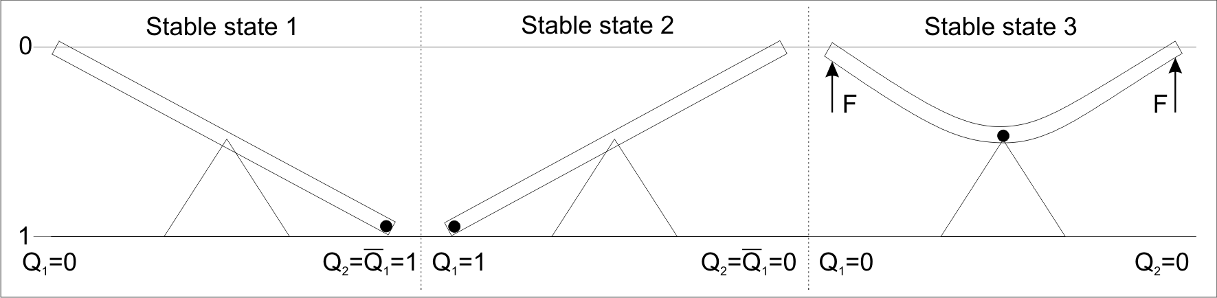
Left picture
With its weight, the ball ensures that the position is stable (reset). If a force is applied briefly so that the rocker tilts,
so the ball rolls to the left position.
Middle picture
Here, too, the ball ensures that this position remains stable, even if the force is no longer acting. (set)
Right picture
If a permanent force acts on both ends of the rocker, both ends of the rocker are moved upwards ("0") and
remain in this stable state while the ball moves to the center. Now the force is exerted on one of the rocker ends
eliminated before the others, everyone knows what is going to happen. A previously definable final state is reached.
However, if both forces are eliminated at the same time, a brief instability occurs. Both
ends of the rocker swing back to the horizontal and the ball will randomly "decide" into which end position it rolls,
in order to achieve a stable final state again.
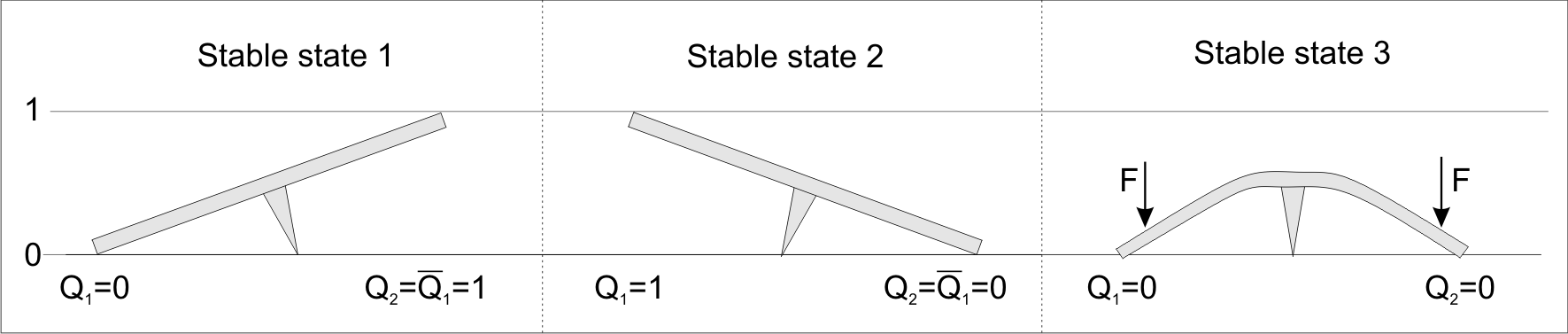
Rocker example 2 is also possible
Here the situation is stable in the first two pictures because the left or right torque is greater than that on the other side.
RS flip-flop animations
All of the Wikipedia media listed above have the same lousy animation. This can very easily be dispensed with. It will though
indicated in which branch a collector current flows after an input pulse has been generated, but how the input and
Output signals behavior is concealed. Furthermore, it is difficult to see why the fliflop remains in the respective position.
The implementation of the input assignment R = S = 1 is complietely ignored.
That is why there is now also a own animation that shows everything that is necessary in order to understand the complete
reaction of RS flip-flops.
A simulation / animation of the RS flip-flop in transistor-transistor logic
With this animation, the correct functioning of the RS flip-flop can be seen and understood very well.
The input assignments can be varied as
required by clicking on the switches. The decisive current flows are shown.
A good and complete animation, however, requires a browser that fully supports scalable vector graphics.
Firefox, Chrome, Safari, for example, are very suitable.
| Signal | R, S | Q1, Q2 |
| 0 | ≤0,8V | ≤0,4V |
| 1 | ≥2,0V | ≥2,4V |
Nobody will find a better animation!, because
1. the RS flip-flop is actually simulated by 2 NOR gates,
2. all input assignments can be modified as required,
3. the output signals match the reality,
4. the real (true) reaction of the flip-flop can be understood from the recognizable currents.
So everyone sees what is actually happening and not what unrealistic, learning-resistant website operators and teachers see to you
try to pretend.
Conclusion
All previous doctrines (see starting page, point 1.) and countless websites have one thing in common:
The truth tables and descriptions
are models that provide for the case R = S = 1 (NOR gate), how this case is to be treated, regardless of the actual circumstances on
concrete object, i.e. unrealistic and therefore simply wrong.
That must lead to contradictions, since the reality
does not depend on the models.
In all of these cases, only a limited function of this circuit is considered.
The various Wikipedias show that there are sometimes considerable differences in the views. The Russian Wikipedia is the best
represents the real properties of the RS flip-flop. The others show a partially great lack of expertise.
Caution is advised when using "ready-made" RS-FF blocks in simulation programs.
In such cases it is better to build such a module yourself with 2 correspondingly interconnected NOR or NAND gates.
This homepage shows how a general correct definition and description of the RS flip-flop can look like.
My new circuits shown on the following pages for an 'ideal pulse circuit' and a 'non-clocked (asynchronous) JK flip-flop'
prove the correctness of my statements. These are still supported by the
Analysis report by Mr. Stefan Dumler.