


An ideal pulse circuit
Pulse circuits described in this text are such circuits to generate temporally limited pulses for instance to set or reset flip-flops. RC-combinations like shown in fig.2 are widely used for this application. A 1-signal to the RC combinations produces only one pulse to the S-and R-inputs of the flip-flop, which is sufficient to switch the flip flop in the corresponding state.
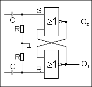 Fig. 2 RS flip-flop with RC-combination
The time constant t=RC follows 2 contradictory requirements:
- t must be large enough, to realize a reliable switch.
- t must be small enough, to discharge the capacitor in a short time, to reach a high cut-off frequency.
It has to be found a compromise.
Such a RC-combination limited the cutoff frequency strongly.
Basis requirements for an ideal pulse circuit for this object
| 1. Form of the pulse: | rectangular. |
| 2. pulse duration: | as short as possible or as long as necessary. |
| 3. cut-off frequency: | as high as possible |
The ideal pulse circuit should have an additional property, but their significance is only at the later application of clearly recognizable:
It should not create a further pulse as long as there is no need to do it. That is, if the RS-FF is set, no further pulse will be created until the FF was reseted. The same applies to the reset-function.
Such an ideal pulse circuit shall be described now. To reach the optimal pulse duration, the feed-back of the switching caused by the pulse itself is used.
You will find the circuit diagram of the ideal pulse circuit in Fig. 3.
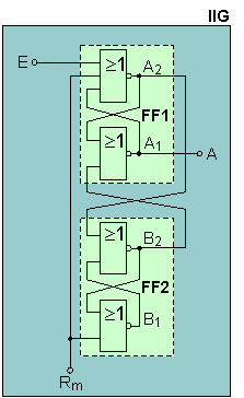
It consists of the RS flip-flops FF1 and FF2.
It has one input E, which can activate (1) the output A dependent on certain conditions.
Input Rm is a feedback signal. Normally it is low(0). After output A has pulsed to high(0->1) and has triggered/released the intended function, Rm pulsed to high(0->1).
Further important properties::
- Only if E is pulsed high (0->1) and Rm=0, output A is pulsed high (0->1)
- Immediate after changing Rm (0->1) output A gets a 0-signal . The device is ready to be activated again as soon as Rm moved back (1->0) and input E is waiting for next pulse (0->1).
Fig. 3 Ideal puls circuit (IIG)
Important Note:
Only when E is pulsed to high (0->1) and Rm=0, output A becomes activate (0->1). If E=1 and Rm is changing 1->0, there is no reaction on the output A!
In fig. 4 you can find a simplified pulse diagram of the ideal pulse circuit.
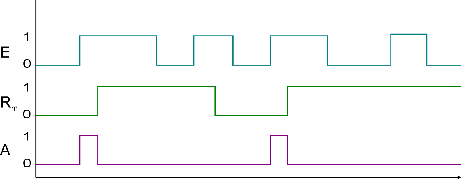
Fig. 4 Pulsdiagram
An ideal pulse circuit for these claims was found!
Obviously the function of this circuit is only possible, while S and R of the flip-flops at the same time can be set to high (1)!
In the following chapter New JK flip-flop/JK latch is an example of application for this impulse circuit.